About the steel boat frame structure
The Keel
The keel is the main structural member and backbone of a ship or boat. The Mimi Jane’s full back bone is formed by its stem, keel, deadwood and stern beam. It’s keel was laid at exactly 5 degree from level as our reference member, so the boats ribs would stand 90 degree from level. The Stem was built to look like a solid wood stem. To say the least, it’s overkill and purely for looks.
The shoe is made of a 10 inch wide C channel, with a 1/2 inch thick web and doubled with an other 1/2 inch thick flat bar; total shoe base of 1 inch.
The Rib
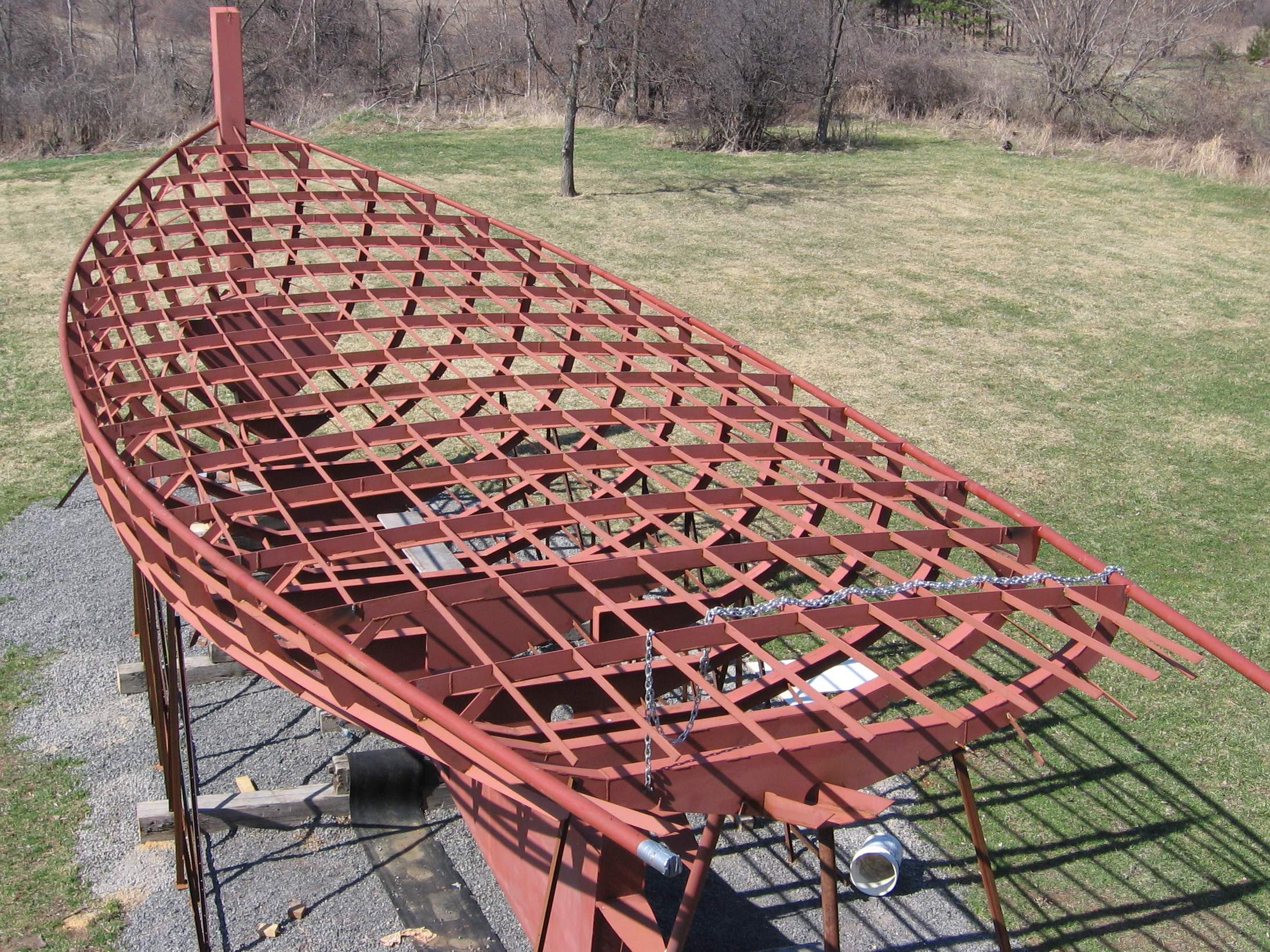
The ribs are the transverse frame members of the boat. Each rib forms a full ring including the floor member and the deck beam. The Mimi Jane has 15 ribs evenly spaced (3 ft apart) and standing perpendicular to the water line. All the ribs were numerically cut out of 1/4 thick plate. They were precisely cut with notches to accommodate the longitudinal frames and draining holes.
The Longitudinals
The longitudinal are the structure running length wise. The longitudinal tie the ribs together and provide stiffness to the plate between the ribs. Our longitudinal frames are made of 2 inch by 1/4 inch flat bar and run from he bow all the way to the stern.
All the structural choices were made to to meet ABS and Transport Canada Structural standards.
Building the keel and stem
Here’s the keel!! We were so exited when that piece of channel was laid. I had been starring at my drawings for so long by then that I didn’t need more to see the boat. It was there, clear and all in shape. I just couldn’t help continuously asking Mark: Do you see it? I may have a lot of imagination because I could see the boat on that channel.
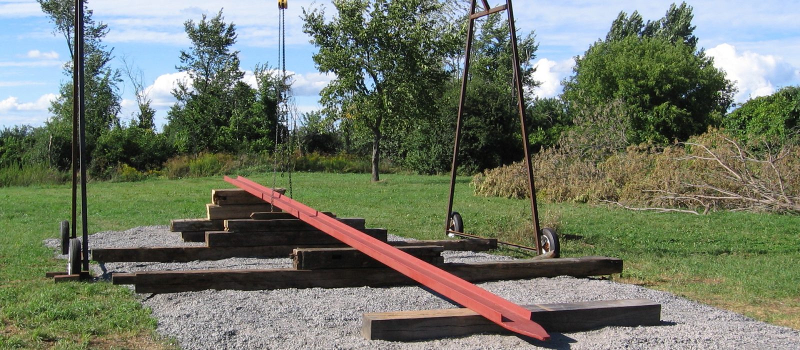
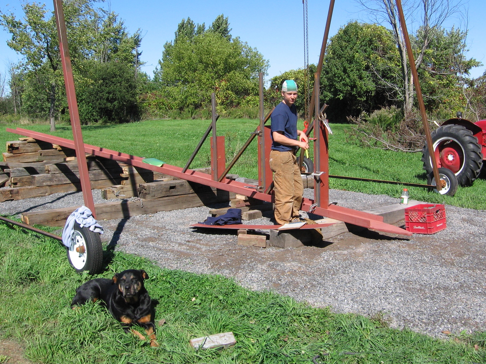
Never less, that single piece of steel was the most critical to position. For any kind of precise assembly you need a reference to which all other elements are localized to avoid adding up error by localizing all element arbitrary to each other. So here was my reference piece, the keel shoe angled at 85 degrees with the orientation of gravity. It turned out to be much more strait forward than I expected to position it. We used a good laser level, a long ruler and a bubble level.
On this picture I’m starting to build the dead wood of the keel which would than provide a strong point to start standing the ribs.
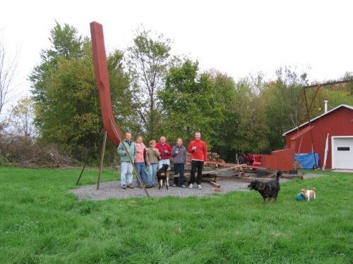
The stem!! I really wanted that piece to look like if it was made out of a solid piece of wood and was willing to do the extra work for that. It couldn’t be a simple box section to look right, I made some bevels like a wood stem would have. Anybody can decide for themselves if it has the looks of wood but for the solid part of things I’m pretty confident it’s solid. I spent a good week making this somewhat phallic sculpture.


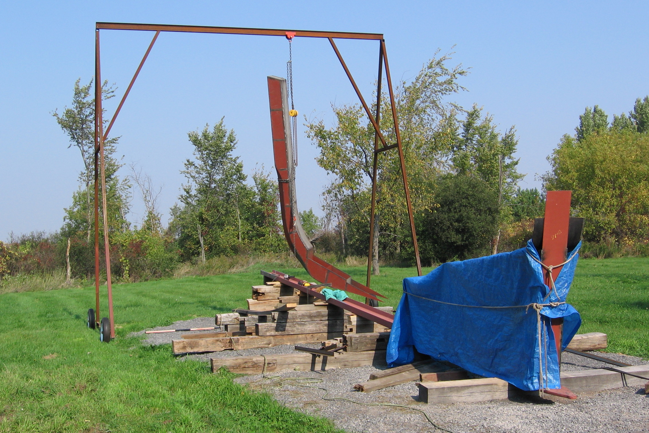
Bringing this out of the shop we had a little choc from the size of it. The stem is over 15 ft high on it’s own so standing 6ft over the ground we were in for a bit of a panic concerning the size of the boat.
Assembling the ribs
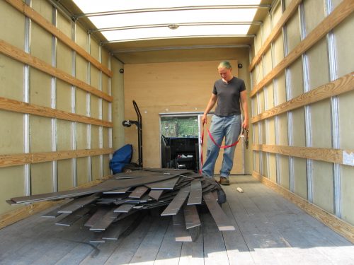
The first load of steel was all flat bar. We would use 2 x 0.25 inch flats for longitudinals, 4 x 0.25 inch for our rib flanges.
The boats shape is mostly defined by its ribs. To achieve as nice of a shape as possible and to facilitate the work was modeled, faired and lofted with CAD software (see design section). From the computer model I had all the rib’s numerically cut.
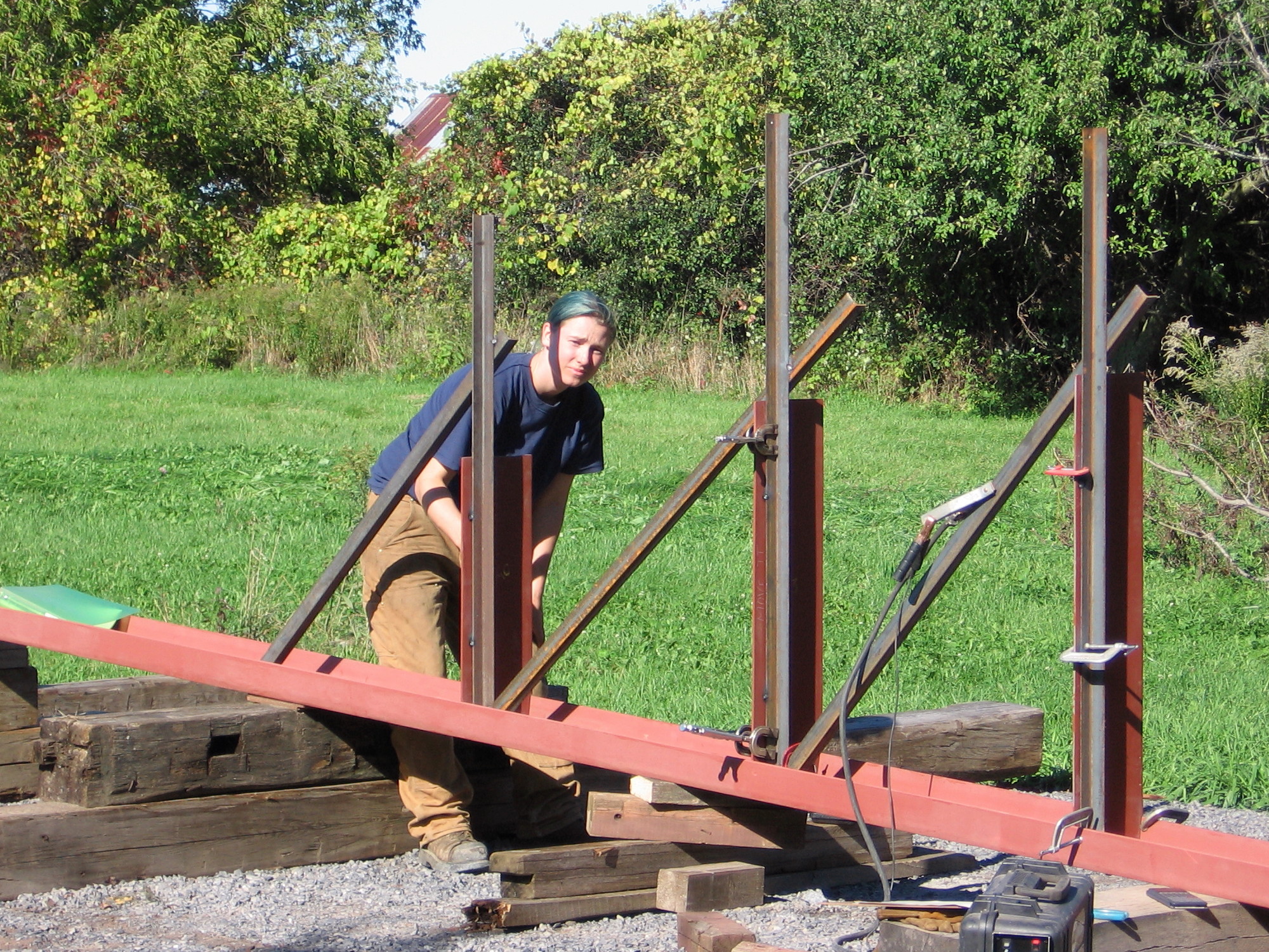
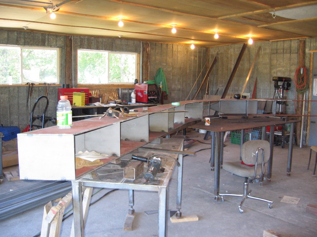
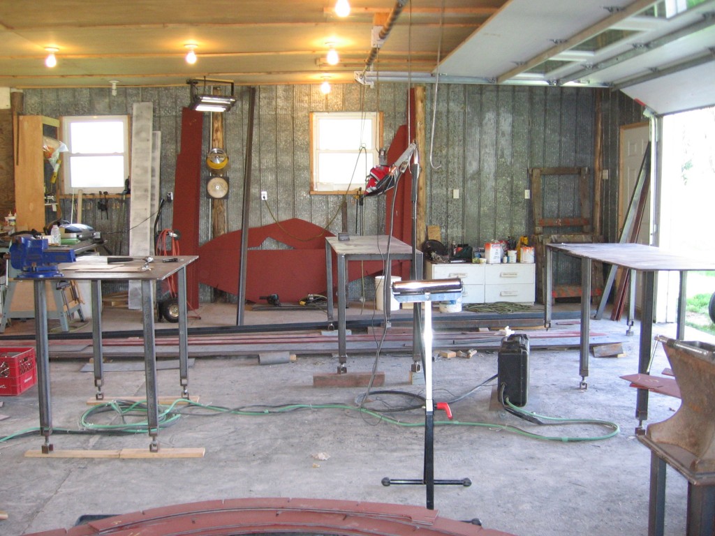
It only took me three weeks to assemble the ribs. Mark was away for work so I just went at it non-stop. Like for the rest of the building, having the boat detailed in CAD was a big advantage, I could double check the dimensions of my frames with multiple diagonals picked out of the computer model. To assemble the ribs, I had previously built four heavy steel tables with adjustable feet. A couple rollers on tripod also helped support longer spanned pieces. Each ring is different so I moved the tables around to support all the parts in a single plane. The more accurately the ribs are built the easiest the rest of the boat assemble will be. I ran the laser level and adjusted the feet each time I moved the tables around (for each rib). Having a perfectly flat floor would have taken all the fun out of the process….
Each rib was divided in two sides, a top (some split in two) and a floor piece; the ribs were pieced to optimize the nesting of the parts for NC cutting and minimize steel (and money) wastage. Knowing myself and how talented I am for mixing up order of things I had not only well identified and numbered all the parts but also “cut” the rib parts so the angles of the mating sides would allow only the proper parts to be assembled with each other. It was somewhat a fool proof puzzle.
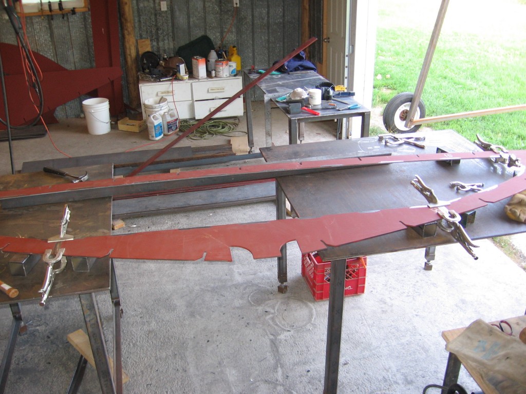
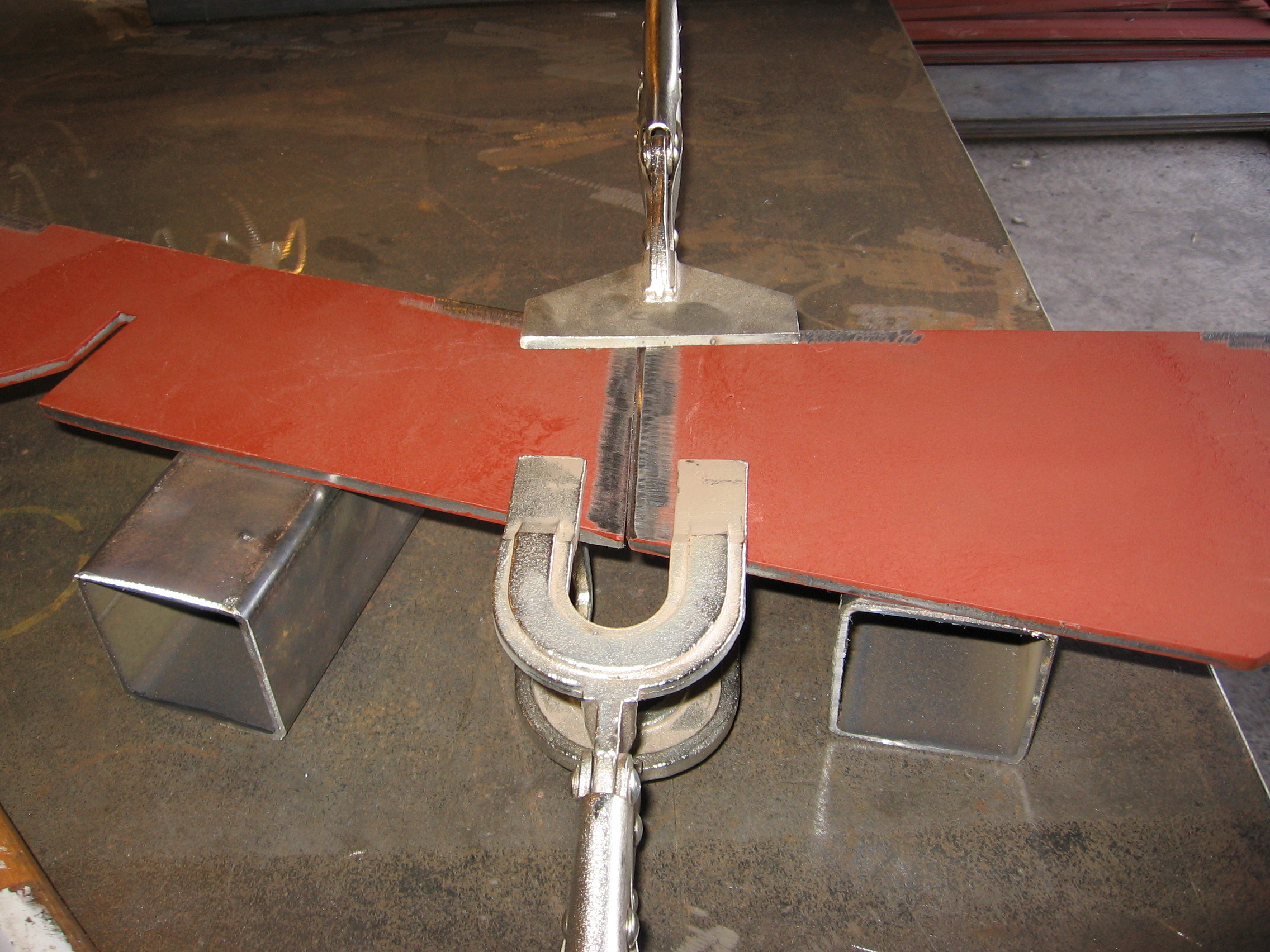
Step two of ring assembly was: welding on a flange. All the centered ribs I made up in T sections, the bow ribs were L sections with the flange on the aft side of the rib and the opposite for the stern; I did so to get a better access under the flanges for blasting, painting and maintenance once the boat is fully assembled. We are hopping a bit of forward planning will make our life easier later. I made up many clamping jigs to position the flanges and help pulling the flat bar strait onto the ring.

Non of this was difficult just long and laborious after the first few ribs and a relief when I got to the fifteenth one. The trickiest part of the job was getting the bigger ribs out of the shop after assembling them. I was on my own to handle those giant rings.
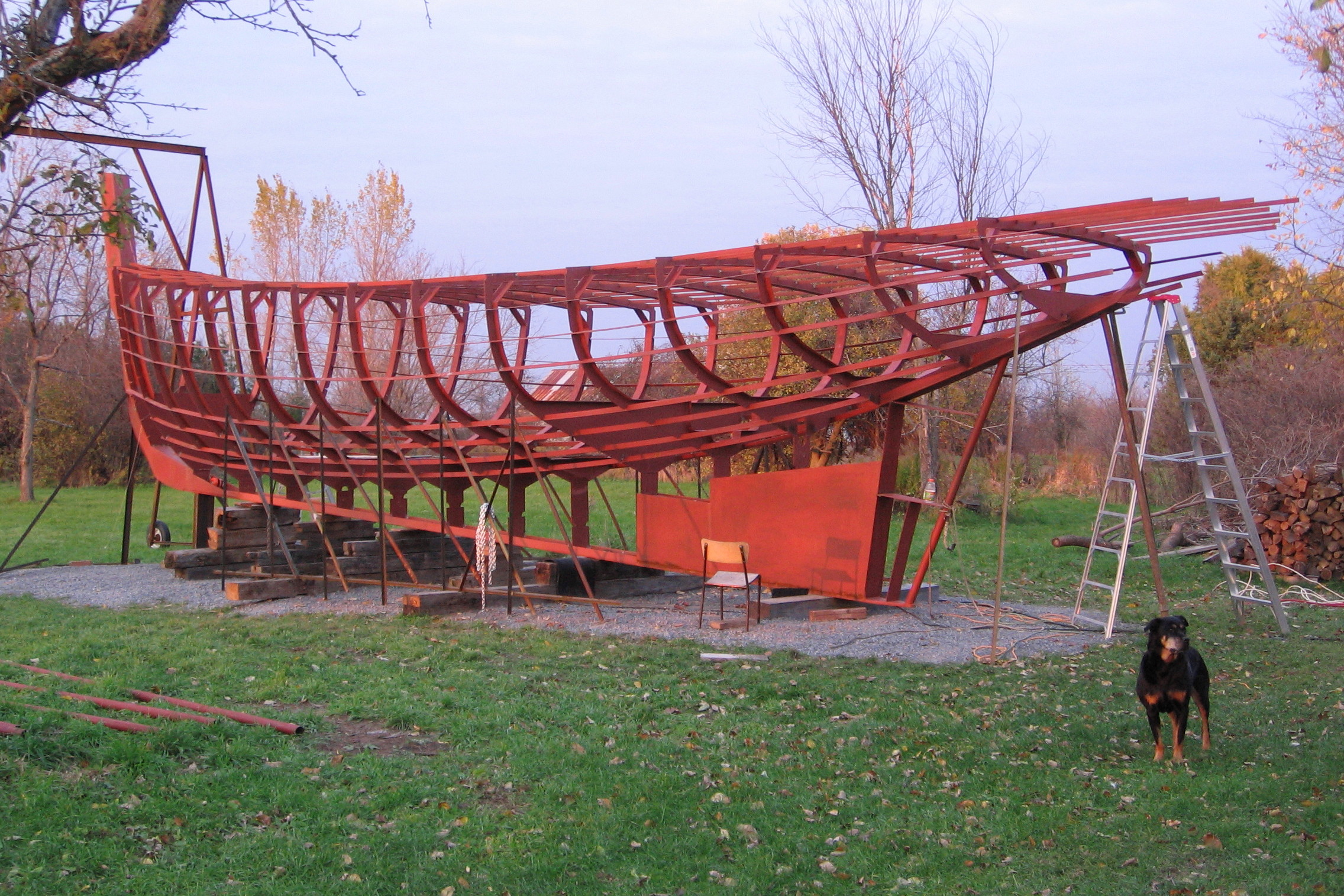
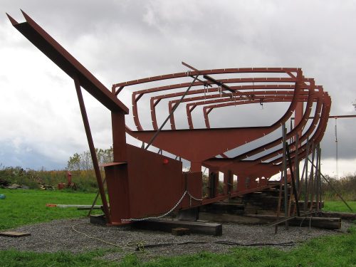
Bringing the frame up
The first rib to be raised was the tenth one (the big one with the big floor, which is meant to become a bulkhead). As I mentioned before, the dead wood was our reference structure and position precisely the ribs, the tenth rib was to be welded against the forward compartment on the deadwood. The first few ribs were held in position by some welded angle iron framing fasten to the beams running under the keel.
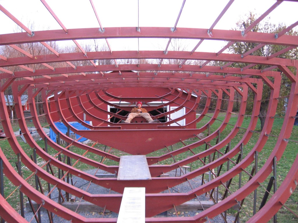
We took great care lining up the ribs. With NC cutting our days it is possible to get accurate rib shape and if positioned right there should be no reason the ribs couldn’t dictate accurately the shape of the hull. Once more, the computer model made it easy. We worked with the laptop in the truck parked beside the boat, pulling out any notch to notch dimension we needed to line up the frames. Each rib was tied to the other and had an external temporarily welded frame to support it until enough of the boats longitudinals would lock everything together. Putting up the ribs was a very stimulating phase of the boat building, it was fast and provided much visual progress, the temperature was cool and dry. Even thoutgh my nerves were making balls in my stomach, it has been my best boat building time up to now. I had drawn and built all those ribs and was terorised by the idea I may have done a mistake at some point, at the same time there was that huge satisfaction to see it come together as planned.
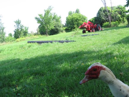
So we worked every day from sunrise to sun set and with a crew of two people, a dog and five ducks (chickens were too busy being chickens) we had all the ribs up within a week.
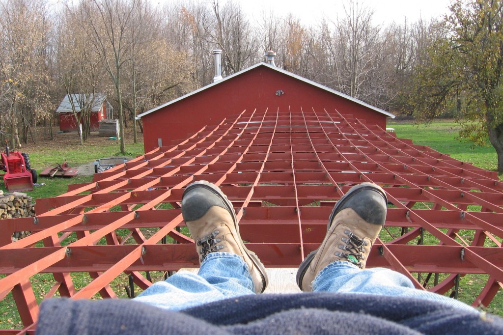
Adding the longitudinals to the frame Its funny how a simple question as which longtudinals are we going to install first can bring in a full reflexion. Every step is fully thoutgh and I probably can give a reason for every step, order or detail. Maybe I shouln’t think so much but maybe time lost on reflexions is better than time lost fixing a mistake. All that to say that we started by locking in the deck longitudinals starting by the center. Before it is a full structure the boat frame can get distorded, the idea is to start by adding the structures that add stability without forcing the frame out of shape. The deck longitudinal litteraly dropped in the notches on most of the ribs and would only need a bit of pulling for the rest.
The hull longitudinals followed, alternating one on one side and the corresponding longitudinal on the other side to keep forces balanced. Was keeping forces balanced an issue at this point for such a structure? I don’t know, maybe not….but what if it was, it didn’t make it any more trouble to follow an order.

The longitudinals went easily in to the notches for most of the boat. The only trouble occurred in the bow where they would trip to much ahead of the second rib for my liking. We solved the problem by chopping the flat bar at the second frame and making new pre-bent pieces for ahead of it. The problem wasn’t worth crying over, it only meant a little bit of extra work. I have since paid a special attention at the longitudinal frames in other steel vessels that I visit or see pictures of and noticed most boats have tripped longitudinals in the bow. Does that mean I shouldn’t of been bothered by a bit of wobble? Maybe, but if I was to design an other hull I would plan ahead for some NC cut stringers for the bow and not even try going against the steels will.
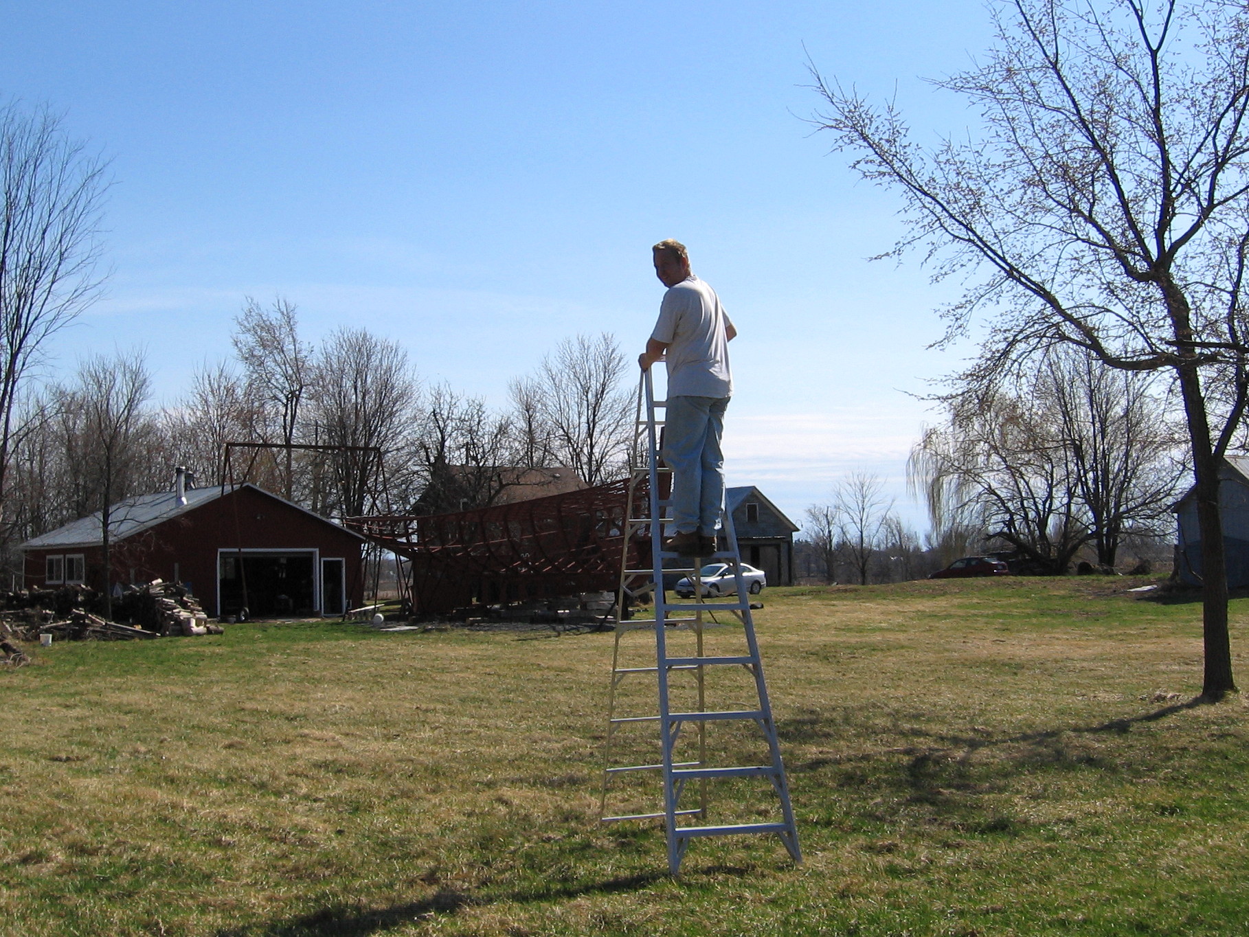
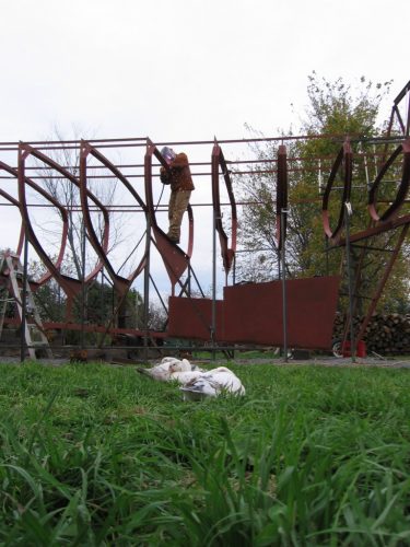
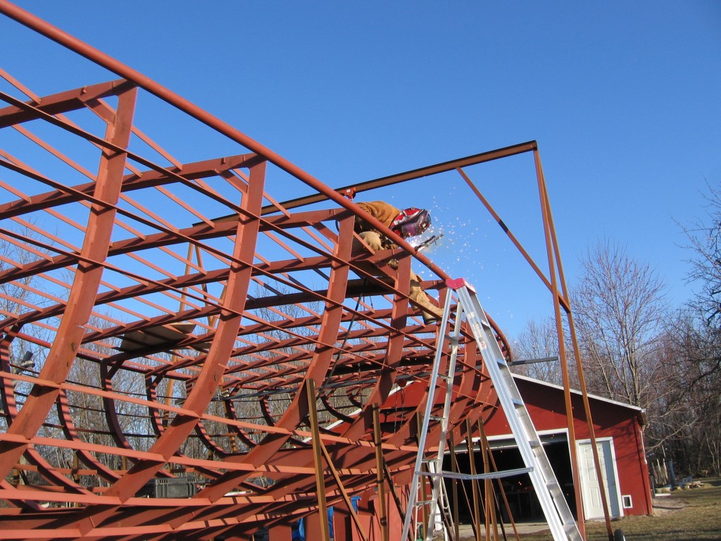
The last lengthwise frame are the deck pipes. It was a charm fitting those in there grooves in the ribs. As each rib met the pipe on a different angle, so each groove would have a different elliptical shape drawn from the intersection of the pipe and the rib on CAD. Once more, it was neat to see the shapes mate as planned. We started from the middle of the boat and went are way to the ends. On this picture I’m trimming the end to match the bow. I’m also secretly enjoying the monkeying in my giant play structure, did I ever climb, swing, balance…play in the frame. It can’t only be work. This picture also shows the break between the stringers and the new bow longitudinal.

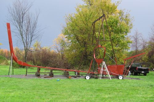
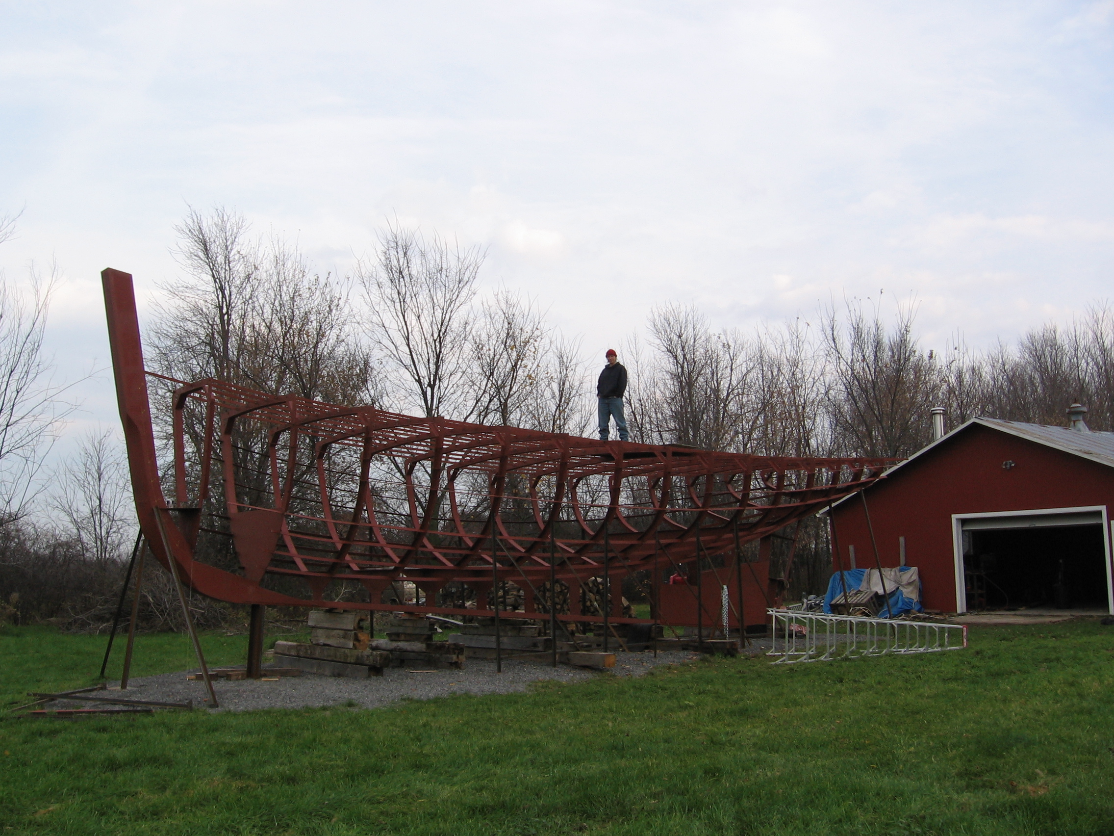
After three weeks of framing, we got something that really recalls a boat. Better than that it looks like the cad model. I don’t know how many times and why I got so surprised how the real thing matched the drawings. …maybe a little bit of lack of confidence…